Diplex Filters ( CATV and MATV Band Splitters/Combiners )
CATV Sub to TV Diplexers ( Return Path / TV Band )
General Purpose Diplexers ( 5 to 1000 MHz )
Table: Standard Diplexers at a Glance
Baseband: Audio / Video Diplexer ( DC to 4.2 / 4,5 MHz )
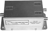
Power Inserter: AC/DC and RF (5-1000 MHz)
Custom Diplexers ( 5 to 1000 MHz )
Sub-TV / TV-Band Diplex Filters for Cable TV
LH7S-40/50 and LH7S-48/54 - Diplexers for 2-way TV systems
High performance band splitter/combiners, designed to provide two-way capability for CATV systems. LH7S-series consist of lowpass and highpass filters joined together to separate or combine the sub-TV band (return path) and TV band (forward path).

4.0"L x 2.5"H x 2.125"W
4.25"L x 3.25"W x 2.5"H(outdoor)
- Low insertion loss and Good return loss
- Excellent isolation between frequency ranges
 LH7S Graphs
 Basic Specifications list:
LH7S- 40/50 |
LH7S- 48/54 |
||
|
|
||
Common Specifications: |
|||
|
|||

Example Graphs
General Purpose Diplexers: CATV / MATV Band Splitter / Combiner
LH7 Diplexer : Dim 1.75"H x 19"L x 3"D

Outdoor Diplexer:
Dim: 4.25"L x 2.5"W x 3.25"H
LH7 Series
LH7-series consists of a dual set of filters - lowpass and highpass with a common port - designed to combine two signals (low and high bands) into one output, or, separate the TV/RF spectrum into low and high bands.
- Low insertion loss (< 1.5 dB), high isolati0on between the frequency bands(>40 dB)
- Variety of models available - click for Table of Diplexers
- Custom models available including option for 50 ohms SMA, BNC, N connectors
General Specifications
| Bandwidth | 0 to 550 / 750 / 860 / 1000 MHz |
| Custom cutoffs (see fig.1) | Fc1 and Fc2 (3 dB cut-offs) |
| Fc1 = lowpass cut off, and Fc2 = highpass cut of | |
| Fc1 and Fc2: | available between 5 to 800 MHz |
| Passband loss: | 1dB ± .5dB, except < 3dB at Fc1 & Fc2 |
| Guard band: | Fc1 and Fc2 are frequency separated by 10 % Example: Fc1 = 300 MHz, Fc2 = 330 MHz ( i.e., 300 x 1.10 = 330 ) |
| Return loss: | 14dB typical |
| Mutual Isolation: | > 40 dB (10 % guard band) |
| Connectors / Impedance: | F-type female / 75 ohm |

Example Graphs
Order Info: ask for model LH7- ( Fc1 / Fc2 )
Specify: Fc1 & Fc2 * ( Fc1 = 3 dB Lowpass cutoff; Fc2 = 3 dB Highpass cutoff )
* Guard band between Fc1& Fc2 is minimum 10% frequency separation
Options for standard LH7:
- Operating bandwidth: 1000 MHz
- Connectors: BNC (75 ohms)
- Outdoor model: specify LH7X
- Lowpass port is AC/DC passing ( DC block optional )
- Highpass port is not AC/DC passing ( Power pass option - 2 amp max, operating bandwidth is 750 MHz max)
Table: Standard LH7 models
Standard LH7 models are listed below. They can be modified for your special requirements.
| Model LH7- (Fc1/Fc2) | Passband Low port (MHz) | Passband High port (MHz) | Mutual Isolation | Band Separation (Freq) * |
| LH7 - 10/14 | 0 to 10 | 14 to 750 | 40 dB min | Sub / TV, 4 MHz |
| LH7 - 33/43 | 0 to 33 | 43 to 750 | 40 dB min | Sub / TV, 10 MHz |
| LH7 - 40/50 | 0 to 40 | 50 to 750 | 40 dB min | Sub / TV, 10 MHz |
| LH7 - 48/54 | 0 to 48 | 54 to 750 | 35 dB min | Sub / TV, 8 MHz |
| LH7 - 65/88 | 0 to 65 | 88 to 750 | 40 dB min | VHF / Low, 23 MHz |
| LH7 - 70/83 | 0 to 70 | 83 to 750 | 30 dB min | VHF / Low, 13 MHz |
| LH7 - 88/108 | 0 to 88 | 108 to 750 | 35 dB min | FM, 20 MHz |
| LH7 - 126/156 | 0 to 126 | 156 to 750 | 40 dB min | CATV / Mid, 30 MHz |
| LH7 - 175/217 | 0 to 175 | 217 to 750 | 40 dB min | VHF / High, 42 MHz |
| LH7 - 210/228 | 0 to 210 | 228 to 750 | 30 dB min | VHF-Hi / Sup, 18 MHz |
| LH7 - 230/470 | 0 to 230 | 470 to 900 | 50 dB min | VHF / UHF, 240 MHz |
| LH7 - 240/258 | 0 to 240 | 258 to 750 | 30 dB min | CATV Sup, 18 MHz |
| LH7 - 300/330 | 0 to 300 | 330 to 750 | 35 dB min | CATV Sup / Hyp, 30 MHz |
| LH7 - 470/520 | 0 to 470 | 520 to 800 | 35 dB min | UHF, 50 MHz |
| LH7 - 500/550 | 0 to 500 | 550 to 750 | 35 dB min | CATV / Hyp, 50 MHz |
| LH7 - 600/660 | 0 to 600 | 660 to 750 | 35 dB min | CATV / Hyp, 60 MHz |
| LH7 - 750/850 | 0 to 750 | 850 to 1000 | 35 dB min | CATV / Hyp,100 MHz |
Baseband Diplex Filter ( Audio and Video Splitter / Combiner )
 LH7 4.2/4.5
 Dim 2.25"H x 5.5"L x 6.5"W
LH7 4.2/4.5
Diplex filter consists of a video lowpass and audio bandpass. High quality base band splitter/combiner, is designed to combine 0 to 4.2 MHz and 4.5 MHz signals, or, separate composite source into video and audio signals. Specifications include
- Common port: 0 to 6 MHz passband
- Video port - Passband loss: < 1.0 dB (0 to 3.5 MHz) and <3.0 dB at 4.2 MHz
- Video port - Return loss (0 to 3.8 MHz): 15 dB min
- Relative Group Delay - 0 to 3.58 MHz: <300 ns
- Audio port - Passband Loss: < 5 dB
- Audio port - Return Loss (4.5 MHz): 15 dB min
- Mutual Isolation: 30 dB min
- Standard Connectors: F-type female, 75 ohms
- Optional Connectors: BNC, 75 ohms
Power Inserter AC/DC and RF Diplex Filter (DC-1000 MHz)
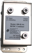
DR-82-2A or 4A
Dim 2.25"H x 4.0"L x 2.125"W
DR-82 Power Inserter (Bias Tee)
Diplex filter, DR-82, is designed to combine or separate AC/DC and RF signal (5-1000 MHz). Available with 2 amp and 4 amp capacity, without fuse, with fuse or circuit breaker. DR-82 features include:
- Low thru loss RF passband (0.75 dB typical)
- AC/DC to RF isolation >55 dB
- Return loss (5-1000 MHz): 18 dB typical
- Relative Group Delay - 5 to 1000 MHz: <20 ns
- Power INPUT can be fused for 2A or 4A current
- Circuit Breaker Option available for 4 Amp model
- Standard Connectors: F-type female, 75 ohms
- Optional Connectors: SMA, BNC, N, 50 ohms