FM Filters & Traps (88 MHz - 108 MHz)
FM Narrow-Bandpass Filters
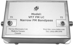
NF7 series Fixed frequency FM Bandpass, and, VF7 series Tuneable FM Bandpass
These filter pass a very narrow portion of FM band and attenuate all out-of-band carriers.
NF7-FM-HQT Passband: <0.5 MHz
- High selectivity: 20 dB rejection at Fc +/- 1 MHz
- HQ Double Helical resonators design
- Passband: User specify frequency (Fc): 87-110 MHz
- Insertion loss (Fc) : < 3.5 dB; Return loss: >18 dB
- Selectivity: > 20 rejection ± 1.0 MHz from Fc
> 30 rejection ± 2 MHz from Fc - Operating bandwidth: 5 to 300 MHz, Add internal Lowpass opt. 1000 MHz
- Connectors: F-type, 75 ohms (standard)
- Optional connectors: 50 ohms - BNC, N, SMA, TNC; 75 ohms - BNC
- User specified fixed passband is fine tune only(Fc +/- 0.5 MHz)
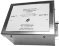
 NF7-FM-HQ
 Dim 4.25"L x 4"H x 1.75"W
NF7-FM-HQ Passband: <1.5 MHz
- HQ Double Helical resonators design
- Passband: specify frequency (Fc): 88-108 MHz
- Insertion loss (Fc) : < 2.5 dB; Return loss: >18 dB
- Selectivity: > 20 rejection ± 2.0 MHz from Fc
> 40 rejection ± 6 MHz from Fc - Operating bandwidth: 5 to 800 MHz
- Factory re-tunable ( 88 to 108 MHz )
- See also CATV filters "Narrow Bandpass"

NF7-FM
Dim 3.6"L x 2.5"H x 3.2"W
NF7-FM Passband: < 2 MHz wide (HQ LC circuits)
- Fixed Passband: user specify FM frequency (Fc)
- Insertion loss (Fc) : < 3.5 dB
- Return loss: >16 dB
- Stopband: > 25 dB rejection ±3 MHz from Fc
- Operating bandwidth: 5 to 750 MHz
VF7-FM LC Passband (<1.5 MHz wide)
- Factory pre-tuned (98 MHz or user-specified)
- Insertion Loss (Fo): <3.5 to 2.5 dB (from 88 to 108 MHz)
- Return Loss: 14 to 18 dB
- Selectivity: >20 dB rejection ±2.5 to 3.5 MHz from Fc
- Operation bandwidth: 5 to 400 or 1000 MHz
- Tunable via two capacitive (mechanical) screw trimmers
- Connectors: F-type, 75 ohms (standard)
- Optional connectors: 50 ohms - BNC, N, SMA, TNC; 75 ohms - BNC
VF7-FM Frequency tunable narrow FM band pass: 1.25 MHz BW

- Factory pre-tuned (98 MHz or user specify)
- Insertion loss (Fo): <3.0 to 2.5 dB (from 88 to 108 MHz)
- Return loss: >16 dB
- Selectivity: >20 dB rejection ±2 MHz from Fc
- Operating bandwidth: 5 to 250 MHz
- Tunable via two capacitive (mechanical) screw trimmers
VF7-FM-HR3 Frequency tunable narrow FM band pass: 1 MHz BW
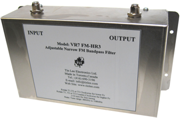
- High Selectivity: >25 dB rejection ±1.5 MHz from Fc
- Factory pre-tuned (99 MHz or user specify (Fo))
- Tunable range 88 to 108 MHz
- Insertion loss (Fo): <3.25 to 2.75 dB (from 88 to 108 MHz)
- Return loss: >16 dB
- Selectivity: >15 dB rejection ±1-1.25 MHz from Fc
- Selectivity: >60 dB rejection DC-80 MHz; 120-1000 from Fc
- Operating bandwidth: 5 to 1000 MHz
- Tunable via three capacitive (mechanical) screw trimmers
VF7-FM-HQT Frequency tunable narrow FM band pass: 0.5 MHz BW
- Highly selective single channel FM band pass filter
- Tunable range 88 to 108 MHz, factory pre-tuned (99 MHz or user specify)
- Insertion loss (Fo): <3.5 to 4.0 dB (from 88 to 108 MHz)
- Return loss: >18 dB (at 98 MHz), 14 dB at 108 MHz, 12 dB (at 88 MHz)
- Insertion Loss and Return loss can be optimized at User specified Fo
- Selectivity: Fo +/-1 MHz rejection >25 dB; Fo +/-2 MHz >40 dB rejection
- Rejection >55 dB 5-80 MHz, 115 to 400 MHz
- Operating bandwidth: 5 to 400 (optional 1000 MHz)
- Frequency tunable via two capacitive (mechanical) screw trimmers

Example Graphs
NF7-FM HQ NF7-FM, VF7-FM, Order Info
Full FM Bandpass models: CF7-CH.FM, BP7-FM and BP7-FM/6
CF7-CH.FM - FM Band pass Filter:
CF7: indoor unit
Dim 4.0"L x 2.5"H x 2.0"W
High quality FM band-pass filter - provides >30 dB out-of-band rejection +/- 10 MHz from bandedge, <1 dB insertion loss. Can be customized for 15 to 25 MHz bandwith, to pass from 80 to120 MHz. Ex: tuned to reject ch.6. CF7-FM (91-108).
- Designed for TV antenna to pass FM band only
- Passband loss: 1.0 dB (except 1.5 dB @ 88 and 108 MHz)
- Stopband Rejection: > 45 dB from 470 to 860 MHz
- Passband can be shifted to pass 92 to 108 MHz, and ch.6 can be attenuated by -20 dB
- Available in outdoor watertight diecast enclosure
- Available in 50 ohms with BNC, SMA, or N connectors
BP7-FM Super Selective FM band pass Filter
- Designed to pass FM band only
- Suppress all signals >50 dB +/- 6 MHz outside of FM band >75 dB rejection 150 to 1000 MHz
- Lower stopband excludes ch. 6 audio
- Operating bandwidth: 5 to 1000 MHz
- Stopband: > 50dB (5 - 83 MHz); >80dB 470 - 860 MHz
- Passband loss: 2dB, and 3dB at band edges
- Available in 50 ohms with BNC, SMA, or N connectors
BP7-FM/6 FM Bandpass with ch.6 rejection ( Pass 90 to 108 MHz)
- Filters FM band for TV/FM systems
- Operating bandwidth 5 to 1000 MHz
- Prevents FM interference on TV band and ch. 6
- Stopband ch.6: >40 dB ( 83.25 to 87.75 MHz )
- Stopband > 50 dB (5 - 83 MHz); >80 dB (470-1000 MHz)
- Passband loss: < 2.5 dB, and loss at band edges - 4dB at 90 MHz and 3 dB at 108 MHz (see graph)
- Available in 50 ohms with BNC, SMA, or N connectors

Example Graphs
Sharp FM Frequency Notches: (Fixed & Tuneable)
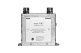
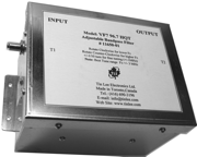
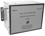
VR7-(Fo) HQ Series
Tunable VHF/CATV/FM Trap
Frequency tunable - suppress one frequency (Fo) using two adjustable trimmers
- Six models covering: VHF low, VHF high, FM, CATV Mid1, CATV Mid2, CATV Super
- Rejection: > 40 dB at Fo <
VR7-(Fo)
Tunable VHF/CATV Trap
- Selectivity Examples:
- 3 dB BW: ± 1.5 MHz (Fo < 200 MHz)
- 3 dB BW: ± 2.5 MHz (Fo < 300 MHz)
- Bandwidth: 5-550 / 10-750 / 40-860 MHz
- Fo: Factory-preset; field tunable via two trimmers
- Rejection: Individual notches are approximately 8 dB
FM Notches (75 ohms, F-connectors, Optional 50 ohms - BNC or N connectors)
FM notch filters are available with five levels of selectivity. Designed to suppress one FM frequency and pass all other signals with low to minimal loss to adjacent carriers. The notches apply for user-specified FM frequencies (Fo).
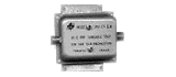
CR7- FM(Fo) HQ - Fixed frequency FM notch 25-35 dB
CR7-FM HQ
Dim: 4.0"L x 2.0"H x 1.75"W
- Attenuation: 25 to 35 dB dB
- Fine tune trimmer to adjust frequency -/+ 0.1 MHz (off tune notch can reduce attenuation up to 15 dB
- Selectivity: 3dB bandwidth is ± 0.75 to 1.0 MHz
- Bandwidth (MHz): 5-300 MHz
CR7- (Fo) HT >30 dB Sharp Fixed Notch
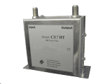
CR7-FM HT
- Attenuation: > 25 dB
- Selectivity: 3 dB bandwidth is ± 0.25 MHz
- Bandwidth: 50 to 220 MHz
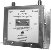
VR7-FM - Tunable FM Notch
- Consists of two tuneable 8 dB notches
- Combined attenuation: > 40 dB
- Selectivity: 3dB bandwidth is ± 1.5 MHz
- Bandwidth: 50 to 220 MHz or 8 to 550 / 750 MHz

Example Graphs
CR7-88.6 HQ (25) and Order info
VR7-FM HT - Sharp FM Notch, Notch Frequency and Depth Tunable
- Sharp and Tuneable FM filter with 88 to 108 MHz tuning range
- Attenuation: User-specified (from 20 to 40 dB)
- Notch Frequency (Fo) is tuneable via two trimmers
- Notch Depth can be adjusted by slight off set of Fo via two trimmers
- Example selectivities:
- 25 dB notch: 3dB bandwidth is ± 0.35
- 40 dB notch: 3dB bandwidth is ± 0.75
- Bandwidth: 50 to 250 MHz
Example Graphs:
VR7-FM HQT, VR7-FM HQTA - Ultra-sharp, Tunable FM Notch
- Ultra-sharp FM frequency notch
- VR7-FM-HQT notch can be easily tuned through the FM band using two tuners
- VR7-FM-HQTA can tune through the FM band using two tuner, and fined tuned (fo +/- 0.1 MHz) with two additional tuners
- Tunable from 88 to 108 MHz
- Optimal range is Fo ± 3 MHz
- Attenuation: User-specified (from 20 to 40 dB)
- Example Notch selectivity:
- 20 dB notch: 3dB bandwidth is ± 0.1 MHz
- 40 dB notch: 3dB bandwidth is ± 0.2 MHz
- Bandwidth: 50 to 200 MHz
Example Graphs:
Multiple FM Notch Filter
VR7-FM-2501-8

- Sharp Multiple FM notch filter with 88 to 108 MHz retuning range
- User specified notch frequencies between 88 to 108 MHz
- The number of notches that can be cascaded is up to sixteen
- Attenuation: User-specified (10 dB to 20dB per notch)
- Combined Attenuation: Combined notches attenuate signal up to 100 dB
- Notch frequency and notch depth are tunable via two screw trimmers
- Bandwidth: 5 to 200 MHz for FM only system
- Bandwidth: 5 to 1000 MHz for OTA/CATV systems
- Applications include:
- Attenuate multiple interfering FM signals
- Equalize Broadband FM signal for distribution
- Specific FM spectrum rejection - up to 2 MHz
- More details -
Antenna FM Bandstop and Bandpass (ATSC models)
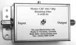
CR7-CH.FM - Bandstop:
CR7: indoor unit
Dim 4.0"L x 2.0"H x 1.75"W
- Designed to prevent FM broadcast interference on off-air TV antenna systems
- Standard attenuations: 30 or 50 dB dB (from 88 to 108 MHz, ch.6 will not pass)
- Passband: DC-82 MHz, 115 to 800 MHz
- Frequency-shifted stopband (e.g.: 91 to 108 MHz) is available to pass ch.6
- Available in Indoor, or, outdoor enclosure
- Available in 50 ohms with BNC, sma, or N connectors
CF7-CH.FM - FM Band pass Filter:
CF7: indoor unit
Dim 4.0"L x 2.0"H x 1.75"W
High quality FM band-pass filter - provides >30 dB out-of-band rejection +/- 10 MHz from bandedge, <1 dB insertion loss. Can be customized for 15 to 25 MHz bandwith, to pass from 80 to120 MHz. Ex: tuned to reject ch.6. CF7-FM (91-108).
- Designed for TV antenna to pass FM band only
- Passband loss: 1.5 dB (88 to 108 MHz)
- Stopband Rejection: > 45 dB from 470 to 860 MHz
- Passband can be shifted to pass 92 to 108 MHz, and ch.6 can be attenuated by -20 dB
- Available in outdoor watertight diecast enclosure
- Available in 50 ohms with BNC, SMA, or N connectors
Example Graphs
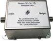
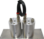
FM combiners: CMN7-FM
CMN7-FM
Custom FM channel combiner or divider. CMN7-FM consists of individual FM bandpass filters joined together at one common port.
- Available for 2, 3, 4 up to 8 channels (88 to 108 MHz)
- FM channels are specified (Fc1...Fc4)
- Total power handling: 40 watts max
- 10 watts per channel for four channel
- FM carrier loss: < 2dB (channel separation >3 MHz)
- FM carrier loss: < 3dB (channel separation >2 MHz)
- Selectivity: > 25dB rejection ±3 MHz Fc
- Isolation between FM channels: > 25dB (channel separation > 3 MHz)
- Connectors: 75 ohms F (female) *
* Connectors/Impedance options: 75 ohms BNC, 75 ohms N, 50 ohms N or 50 ohms BNC
Example Graphs
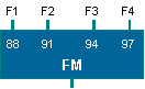
Example: CMN-4 (88/91/94/97) FM
FM signal Splitters (88-108 MHz, 50 ohms)
S7-2FM B50 and S7-4FM B50 (Two-way, Four-way, Ten-Way splitters)

S7-2FM B50 - 2-way splitter

S5-4FM B50- 4-way
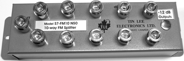
S5-10FM N50- 10-way
- High quality, 50 ohms, FM signal splitters
- Available with 2 to 10 outputs
- Splitter loss: 3.5 dB (two-way), 7 dB (four-way) 12 dB (10-way)
- Isolation between Outputs: >25dB
- Impedance matched: 50 ohms (>25 dB R.L. outputs)
- Impedance matched: 50 ohms (>18 dB R.L. Input)
- Connectors: BNC (F/F) (Optional connectors available: sma, N,TNC)
 PDF S5-FM10 10-way splitter Info Sheet
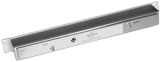
FM/TV band Separator/Combiners
LH7-TF, S7-TV/FM and S7-TV/FM/6
LH7-TF Diplexer (Bandsplitter)
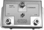
LH7-TF
Dim 4.0"L x 2.0"W x 2.5"H
- FM and Over-the-Air TV bandsplitter (DC-108 MHz and 174-800 MHz)
- Consists of Low pass and High pass filters connected to Common port
- Low pass thru loss: < 0.5 dB @ FM, - compared to 3.5 dB RF splitter loss
- High pass thru loss: < 1.0 dB TV, - compared to 3.5 dB RF splitter loss
- Mutual isolation >50 dB - blocks FM signals entering TV system and vice versa
- Available with F 75 ohms ports, Option: 50 ohms inpedance with BNC, N or sma connectors
S7-TV/FM
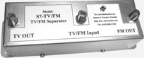
S7-TV/FM
Dim 7.0"L x 2.0"W x 2.5"H
- High quality, Over-the-Air TV/FM band separator/combiner
- S7-TV/FM: TV port ch. 2-5, 7-13, 14-69 ; FM port 88-108 MHz
- S7-TV/FM/6 TV port ch. 2-6, 7-13, 14-69 ; FM port 92-108 MHz
- Combination low loss FM bandpass and sharp 40dB FM bandstop
- FM bandpass -1dB loss to FM signals,and, >55 dB rejection of VHF Hi-UHF TV signals
- FM bandstop -1dB loss to TV signals,and, >40dB attenuation of FM signals
- Separation of TV and FM band has typical 1dB loss, lower loss than RF splitter 3.5 dB
S7-TF
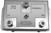
S7-TF
Dim 4.0"L x 2.0"W x 2.5"H
- Over-the-Air TV/FM band separator/combiner (50-800 MHz)
- S7-TV/FM: TV port ch. 2-5, 7-13, 14-69 ; FM port 88-108 MHz
- Combination low loss FM bandpass and 20dB FM bandstop
- FM bandpass -1.5dB loss to FM signals,and, >25 dB rejection of VHF Hi-UHF TV signals
- FM bandstop -1dB loss to TV signals,and, >20dB attenuation of FM signals
- S7-TF has approx. 1dB thru loss, lower loss in comparison to RF splitter 3.5 dB
- Available with F 75 ohms ports
FM Band Matching Transformers (50 to 75 ohms)
 MT-50/75-FM BfFf
Connectors: BNC female/F female/F
Dim:3.5"L x 0.75"D x 1.75"H
MT- 50/75-FM (FM Band: 80 to 120 MHz)
MT-50/75 (FM) is modified version of MT-50/75. It is designed to impedance match 50 ohms FM antenna to 75 ohms receiving equipment. The MT-50/75-FM will optimize signal transfer, prevent impedance mismatch and reduce signal reflection.
- Passband optimized for FM band (pass 10 to 700 MHz)
- Thru Loss (80 – 120 MHz): <0.5 dB
- Return loss is optimized for FM 75 ohms port: >35 dB (VSWR 1.04);
- Return loss is optimized for FM 50 ohms port: >30 dB (VSWR 1.06);
- Connectors: 50 ohms BNC (female) and 75 ohms F-type or BNC (female)
- Rugged, compact casing
- Connectors available for 50 ohms port include: sma. BNC, TNC and N type (female or male)
- Connectors available for 75 ohms port include F, BNC (female or male), and N type female)
- Power Handling: 20 Watts; Operating Temperature: -30C to +40C
Outdoor Antenna Preamplifiers
MA-20-77-ch.FM
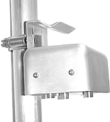
MA-20-77-ch.FM
High quality FM antenna preamplifiers, designed to optimize FM signal reception from the TV antenna to the TV or Headend by providing a stronger signal with improved signal quality.
- Designed for reliable performance
- Bandpass filtered for FM reception
- Low noise figure (3.5 dB) for better FM reception
- Low power consumption & static discharge
- UL approved remote indoor AC power adapter
- 75 ohm models have F-type connectors (F/F)
- Click > Table: Preamplifiers
Indoor FM Distribution Amplifiers
TA-25-FM, TA-36-FM, TA-45-FM
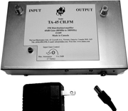 TA-45-FM
High quality FM distribution amplifiers designed to optimize FM signal distribution, providing a stronger signal with improved signal quality.
- Designed for reliable performance
- Available with 25 dB (TA-25-FM), 36 dB and 45 dB gain
- Bandpass filtered for FM operation (>14 dB R.L. Input/Output)
- Optional ch 6 rejection and FM frequency shift 91-108 MHz for CATV systems
- Low noise figure (3.5 dB) for better FM distribution
- Low power consumption & static discharge
- UL approved remote indoor AC power adapter
- 75 ohm models have F-type connectors (F/F)
- Option: 50 ohm models with BNC or N connectors