CF7: Semi-Adjacent Bandpass
Graphs / Specs / Custom Info
Menu
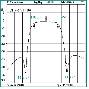
Graphs: CF7-ch. 3 and T10A
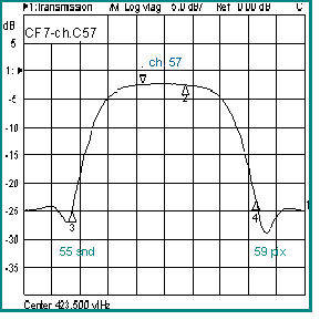
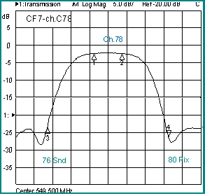
Graph: CF7-ch. 57 and 78
Graph: CF7-series Specifications
Custom CF7 Information
Graph 1 - CF7-ch.3A
Channel 3 Bandpass: Passband loss: 2.5dB
Includes adjacent channel suppression option *

Graph 2 - CF7-ch.T10A
Sub-band Channel : Passband loss: 2dB
Includes adjacent channel suppression option*
Graph 3 - CF7-ch.57
CATV hyperband bandpass
Passband loss: 2.5 dB and > 20 dB stopband
Graph 4 - CF7-ch.78
CATV Ultra-band bandpass
Passband loss 3.5 dB and > 20 dB stopband
Order as: CF7-ch.( # ), outdoor version CF7X-ch.(#)
Specify: channel #, Ex: CF7-ch.C57 (CATV) or CF7-57U (UHF)
Suffix "A " for adjacent rejection (T7 - T13, TV-IF, 2 - 6, A8 - G20); Ex: CF7-ch.3A
CF7 - General Specifications
| Model CF7 Channel No. | Passband Loss (MHz) | Stopband Loss (min)* | General Specifications |
| T7 to T13, IF | <2 dB | >30 dB |
Passband (MHz): 4.5 - 12 MHz (1-2 chs) Passband ripple: ± .5 dB Return Loss: 15 dB typical Operating Bandwidth: 5 to 750 MHz Connectors (std): 75 ohms F-female Optional Connectors: F: male, BNC: female, or N type: female Weight (oz): 6 or 10, 8(outdoor) Dimensions (in): T7 - T13, IF, 2 - 49: 3.6L x 1.75H x 3.4W 50 -140, 14 - 69 UHF: 3.6L x 2.5H x 3.4W Outdoor housing: 4.25L x 3.25H x 2.5W |
| 2 to 6, A8 to A1 | <2 dB | >30 dB | |
| FM ( 88 to 108) | <3 dB | >25 dB | |
| 14 to 22 | <2.5 dB | >30 dB | |
| 7 to 13, 23 to 36 | <2.5 dB | >30 dB | |
| 37 to 46 | <2.5 dB | >25 dB | |
| 47 to 62 | <2.5 dB | >20 dB | |
| 63 to 85 | <3.5 dB | >20 dB | |
| 86 to 116 | <3.0 dB | >20 dB ** | |
| 117 to 140 | <3.5 dB | >18 dB ** | |
| 14 to 36 UHF | <2.5 dB | >20 dB | |
| 37 to 69 UHF | <3.5 dB | >18 dB ** |
* Rejection at ± 8 MHz from band edge.
** Rejection at ± 12 MHz from band edge.
Custom CF7 information
CF7 ch.19/20: customized CF7 bandpass for two channels passband. This example illustrates some custom parameters for model CF7 (see graph & table below)

| Mkr | Freq (MHz) | Attn (dB) | Channel |
| 1 Fc1 | 151.25 | -2.201 | 19 pix |
| 2 Fc2 | 161.75 | -2.554 | 20 snd |
| 3 Fs1 | 135.25 | -46.688 | |
| 4 Fs2 | 167.75 | -48.026 |
- Passband: 10 MHz (2 channels)
- Insertion Loss: < 2.5 dB
- Ripple: ± .25dB
- Cut-off: see Fc1 & Fc2
- Stopband: see Fs1 & Fs2
- Attenuation: > 40 dB
- Transition (Fc/Fs): 16 MHz on lower side, 6 MHz on higher side - can be trap enhanced for narrower transition
- Return Loss: 16 dB typical
- Operating Bandwidth ... 0 - 750 MHz
- Housing: Indoor (outdoor also available)
- Connectors: F-type female Impedance: 75 ohms
- Optional Connectors / Impedance:
- type F (M), BNC (F) - 75 ohms
- types N *, BNC, sma ( F ) - 50 ohms